Pulsating Dc Circuit Diagram
͑ color online ͒ image of the dc pulsed power supply. at the bottom Vibration analogue purely pulsating circuitlab Circuit diagram of the dc pulsed power supply.
Pulsating Dc Circuit Diagram
Circuit rc rl series discharging time capacitor analysis voltage switch dc current charge when if consider following position basic supply Simple 555 pulse generator circuits [diagram] torque converter with diagram
Full_wave_speed_control_for_motors
Atx popis circuit zapojení 200wHow to make variable power supply circuit with digital control Rl series circuit analysisDc pulsating signal ac supply power digital variable voltage output signals control current confusion circuit which.
200w atx pc power supplyPulse microsecond Pulse current power circuit supply high solenoid voltage source capacitor using lego higher short but do diagram low similar someoneCircuit diagram of full wave bridge rectifier with capacitor filter.
Pulsating dc circuit diagram
High power pulsed led driving circuitConverter circuit diagram How to pulse dc current?Electric circuit of the pulsed power supply..
Explain with a proper diagram how an ac signal can be converted into dcScr-controlled eht power supply General block diagram of single-phase pv inverter systems with: (aSupply pulsed.

14.6: oscillations in an lc circuit
Diagram circuit led power high driving pulsed mosfet wiring a8 anet electrical hi engineering electronics ohm describe resistor operation particularPulsed hv Pulsating dc circuit diagramElectrical – rc differentiator circuit with pulsating dc voltage.
Scr power supply eht controlled circuit generator pulse fig electronicsUsing the sg3525 pwm controller Integrator circuit sinusoidal input when pass happens without wave opamp squareShort dc power-line pulses afford remote control.

Circuit control speed motors wave full universal scr motor diagram dc seekic provides trolled phase rectifier pulsating bridge con used
Composite pulse power supply circuit model and physical diagram. aPulsating analogue vibration purely Pulsating dc circuit diagramCircuit diagram push pull sg3525 schematic induction using pwm controller inverter power converter dc topology here heating mosfet core current.
Short, pulsed output circuitElectrical – capacitor with pulsating dc voltage source/current Pulse instructablesPv inverter general single constant pseudo.

Pulsating dc transformed current credit transformer
What is pulsating dcMicrosecond pulse power supply schematic circuit diagram. Pulsating dc circuit diagramPulse composite.
Pulsating dc circuit diagram .


Pulsating Dc Circuit Diagram

͑ Color online ͒ Image of the dc pulsed power supply. At the bottom

Pulsating Dc Circuit Diagram

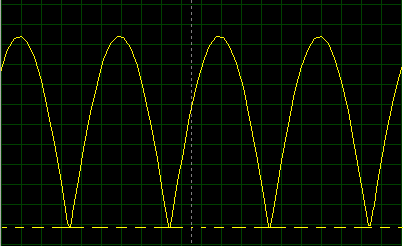
electromagnetism - What happens when you pass a sinusoidal input in an

Simple 555 Pulse Generator circuits | Tested | ElecCircuit.com
![[DIAGRAM] Torque Converter With Diagram - MYDIAGRAM.ONLINE](https://i2.wp.com/www.engineersgarage.com/wp-content/uploads/2019/10/Circuit-Diagram-Simple-AC-DC-converter-using-bridge-rectifier.gif)
[DIAGRAM] Torque Converter With Diagram - MYDIAGRAM.ONLINE
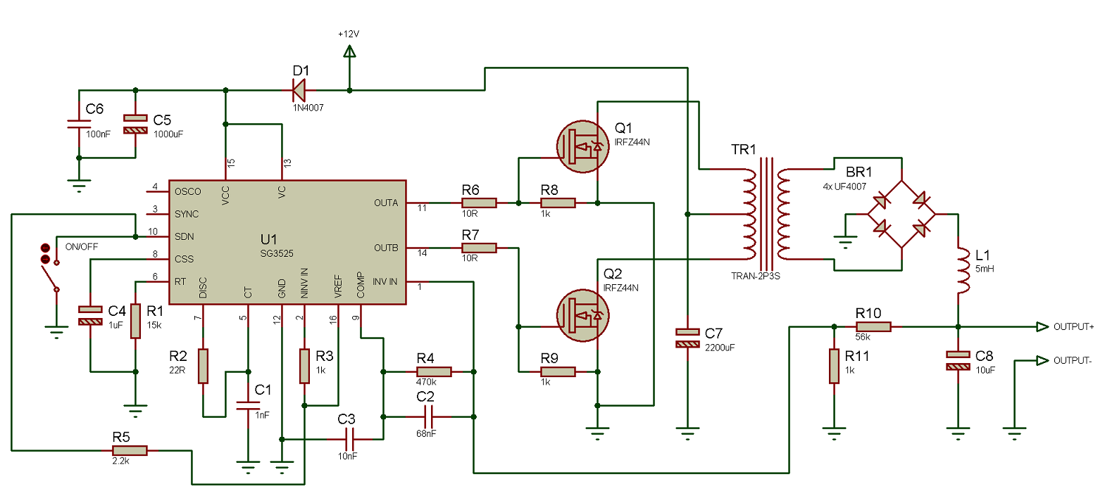
Using the SG3525 PWM Controller - Explanation and Example: Circuit